See part 1
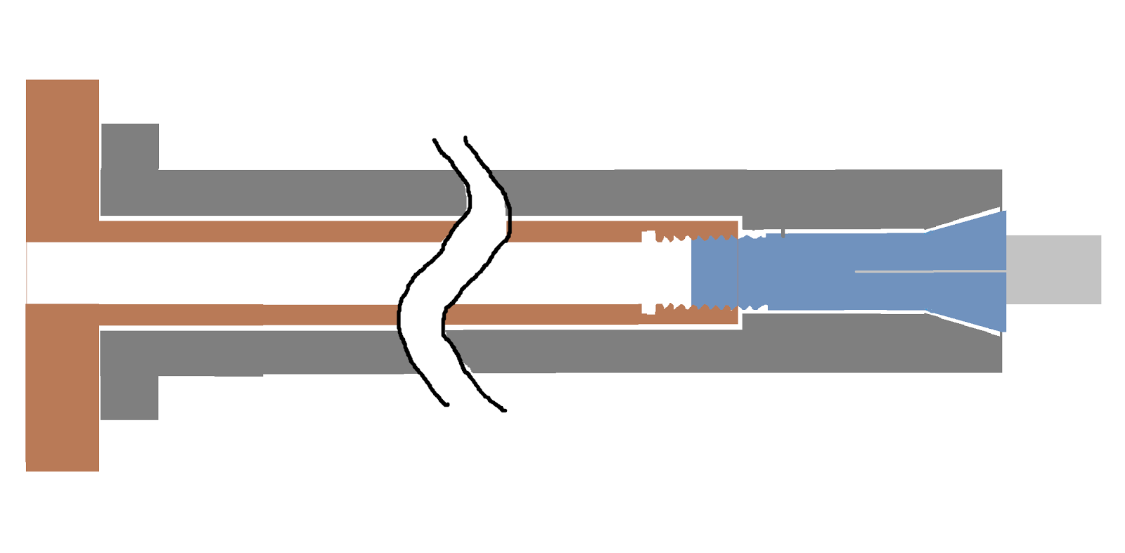
The purpose of the collet draw bar (or in normal cases, draw tube) is to thread onto the collet tightening it onto the lathe spindle and thus securing the stock to be machined. On a normal sized lathe, the draw tube/ bar thing would be a hollow cylinder with a 1.238" - 20 ID thread on on end, and some sort of locking mechanism. Examples of locking mechanisms include lever or pneumatically actuated ones, simple hand wheels (see picture) or more fancy gear driven hand wheels that are closer to the collet circumventing the need for a long tube.
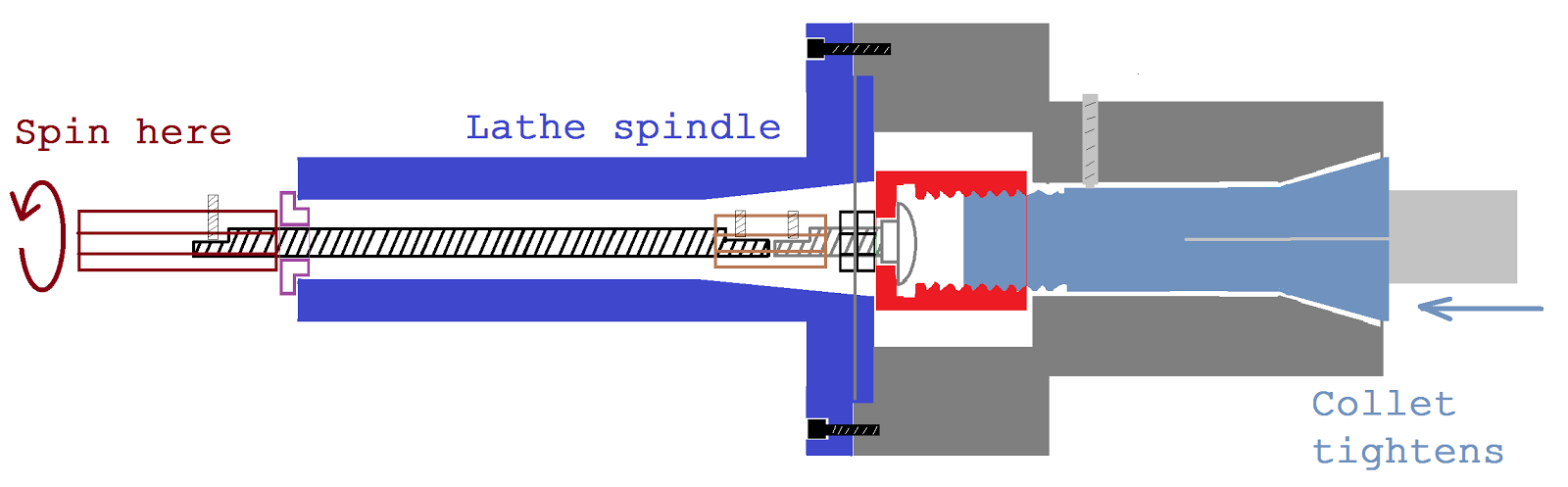
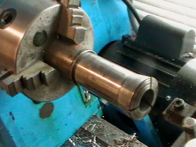
This picture shows an example of what a normal 5C lathe spindle configuration might look like:
In my case, I don't have the luxury of a decent sized spindle bore, so a normal draw tube wouldn't fit through the spindle. In fact, a 5-C collet won't even fit through it. The spindle on my machine was designed with a #3 Morse taper and a 3/4" bore, so if I wanted to do things the "right" way I could drop loads of cash on some #3 Morse collets and use a 3/8" draw bar and we could all be a happy family right? WRONG. #3 Morse collets are too trife to handle the kind of diameters I desire to hold, and furthermore, the whole point of this collet cloture is to hold bigger material even if the machine wasn't supposed to. (I'm not dissing the manufacturers of this machine by any means, I'm confident they designed it for the purpose it was intended for and have every right to make the spindle bore whatever they like. In fact, I actually like the #3 Morse taper as it allowed me to make a nice
wood turning center.) The point is, once you are comfortable working with normal sized machines and their capabilities, and all of a sudden you get a free lathe all to yourself, there is a tendency to expect it to do everything. For that desire,
Scrap Attack comes to save the day.
Instead of a one piece draw tube to secure the collet, I made a short threaded receiver to emulate the threaded end of a normal draw tube, and then constructed a linkage of smaller diameter components so it would fit through the spindle allowing me to tighten it from the back of the headstock. This design doesn't allow really long pieces of stock to extend all the way through the spindle, but you can't always get what you want. I'm not pro enough at cutting gears to make a fancy collet chuck like
this
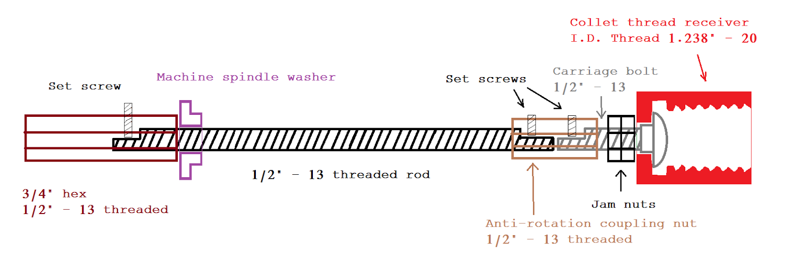
Here is a detailed picture of the draw bar and all of the components. The reason for half of the complication here is because I couldn't find a 2 foot carriage bolt, so I instead linked a carriage bolt to a piece of threaded rod by making a coupling nut with set screws to secure onto flats milled on the bolt and rod. Similarly, the 3/4" hex on the back end secures on the same way, except this has to be removable so I can pull the thing through the spindle when I want to take the collet cloture off. I chose a 3/4" hex as the actuating mechanism because it is simper than making a hand wheel, and also it is familiar to the draw bars on a milling machine. (This particular 3/4" hex was actually from a scrap milling machine draw bar, the school had lots of them since people in the intro class think they have to exert all their strength when tightening the draw bar, and strip the threads. DON'T BE A HERO, YOU DON'T NEED TO TIGHTEN IT THAT MUCH.)
Here we go!
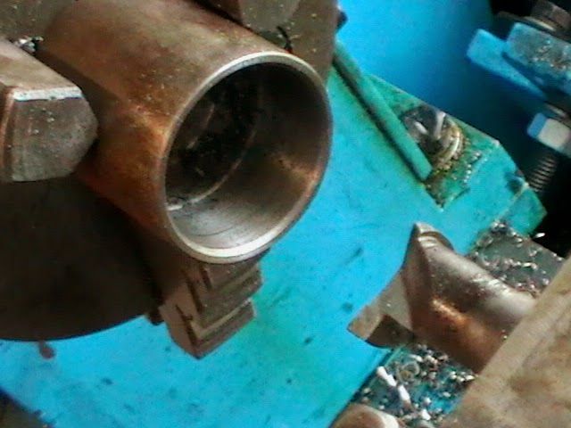
First up, the most important piece, the collet thread receiver. This was made of 1.375 stock.
Facing.
Starting the hole.
Opening up the hole with a large drill.
Using a small tipped boring bar to remove the conical shape at the bottom of the hole left from the drills. I think this is when I bored the hole for the 1/2" carriage bolt as well.
With a larger, more rigid boring bar, boring the hole to the thread's minor diameter.
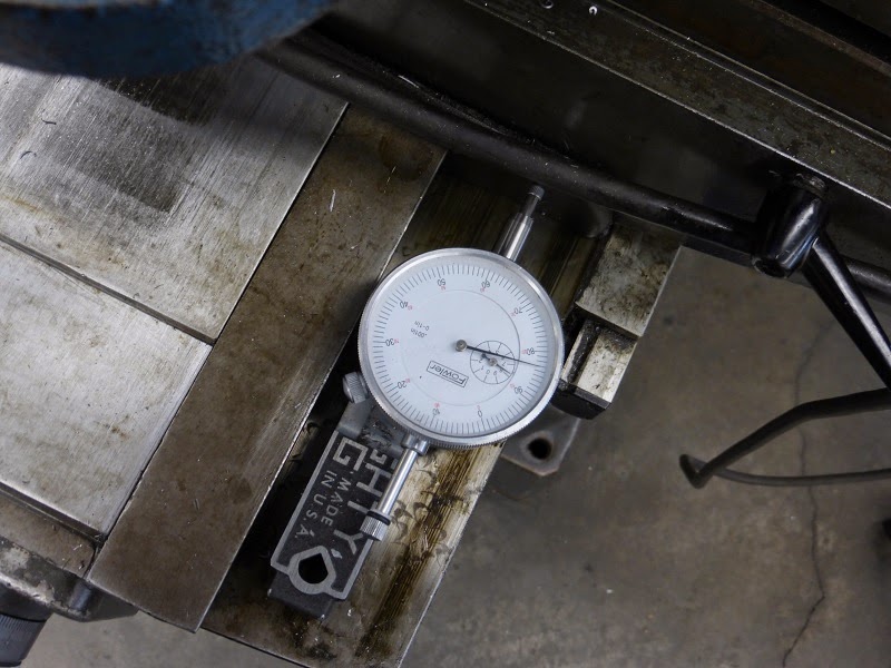
Using an I.D. groove tool to cut the thread relief.
Using a dial indicator to ensure the thread relief was cut deep enough. I couldn't think of any other way to measure an I.D. groove.
Cutting the threads with and I.D. threading tool. This is one of my least favorite operations since it is hard to see inside, but fortunately this tool made it easier since it is facing away. This meant the spindle was run backwards and the tool was fed from the inside out avoiding the danger of accidentally crashing the tool into the shoulder.
I must've gotten lucky since the thread came out perfectly to fit onto the collet.
Then a little cleanup of the O.D.
Cleaning up the other half of the O.D.
Time for some math. The square part on the carriage bolt isn't perfectly square as it has rounded corners and tapers a bit. I measured it diagonally to figure out the radius size, and from this dimension, I figured how small of an end mill I'd have to use to cut an adequate square.
Indicating the part on center.
The first corner being plunge cut.
Using dial indicators to ensure the dimensions were correct since the backlash on the hand wheels made then untrustworthy. And once again, because digital readouts are for sissies.
Cutting all the way around. The
wrath of the math ensured there would be no sharp corners to relieve.
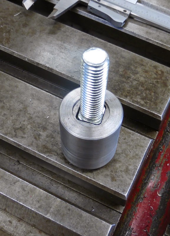
A good fit. Notice the slight counter bore around the square hole. This was from a failed attempt to make the linkage more precise with a washer and other stuff that wasn't even necessary. I decided it would be best if the jam nuts didn't actually tighten up against the thread receiver, allowing a bit of play for the collet's taper to dictate the concentricity instead of a rigid draw bar.
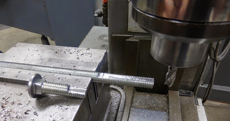
Milling the flats on the carriage bolt and threaded rod.
All the real action is done at this point, here are the other parts being made.
The 3/4" hex for the wrench:
The coupling nut:
The coupling nut (and the wrench hex) were tapped for 1/4" - 28 set screws since there was little thickness for the threads. This one is 5/8" hex stock because it had to fit inside the lathe spindle opposed to the 3/4" wrench hex which goes on the back of the spindle.
The spindle washer/spacer/bushing thing:
Now that all of the parts are done, here is the final thing assembled. This inserts through the front of the spindle before the collet cloture is screwed on, then the wrench hex is secured afterwards. Sadly, I actually forgot to insert the draw bar a couple of times when installing the collet cloture which was an inconvenience since those cap screws are quite laborious to undo with that short Allen wrench.
View of the back of the spindle of the wrench hex with washer. It should be noted that I drilled a hole in the side of the collet cloture to insert a rod to prevent the spindle from spinning when tightening the draw bar.
Back to part 1


nice it is finisch?
ReplyDelete